
Skip Nav Destination
Close Modal
Search Results for
fatigue crack initiation
Update search
Filter
- Title
- Authors
- Author Affiliations
- Full Text
- Abstract
- Keywords
- DOI
- ISBN
- EISBN
- Issue
- ISSN
- EISSN
- Volume
- References
Filter
- Title
- Authors
- Author Affiliations
- Full Text
- Abstract
- Keywords
- DOI
- ISBN
- EISBN
- Issue
- ISSN
- EISSN
- Volume
- References
Filter
- Title
- Authors
- Author Affiliations
- Full Text
- Abstract
- Keywords
- DOI
- ISBN
- EISBN
- Issue
- ISSN
- EISSN
- Volume
- References
Filter
- Title
- Authors
- Author Affiliations
- Full Text
- Abstract
- Keywords
- DOI
- ISBN
- EISBN
- Issue
- ISSN
- EISSN
- Volume
- References
Filter
- Title
- Authors
- Author Affiliations
- Full Text
- Abstract
- Keywords
- DOI
- ISBN
- EISBN
- Issue
- ISSN
- EISSN
- Volume
- References
Filter
- Title
- Authors
- Author Affiliations
- Full Text
- Abstract
- Keywords
- DOI
- ISBN
- EISBN
- Issue
- ISSN
- EISSN
- Volume
- References
NARROW
Format
Topics
Book Series
Date
Availability
1-20 of 605 Search Results for
fatigue crack initiation
Follow your search
Access your saved searches in your account
Would you like to receive an alert when new items match your search?
1
Sort by
Series: ASM Technical Books
Publisher: ASM International
Published: 01 August 2005
DOI: 10.31399/asm.tb.mmfi.t69540379
EISBN: 978-1-62708-309-6
... Abstract This appendix presents an analytical model that estimates damage rates for both crack initiation and propagation mechanisms. The model provides a nonarbitrary definition of fatigue crack initiation length, which serves as an analytical link between initiation and propagation analyses...
Abstract
This appendix presents an analytical model that estimates damage rates for both crack initiation and propagation mechanisms. The model provides a nonarbitrary definition of fatigue crack initiation length, which serves as an analytical link between initiation and propagation analyses and appears to have considerable merit in estimating the total fatigue life of notched and cracked structures.
Image

in Sources of Failures in Carburized and Carbonitrided Components
> Failure Analysis of Heat Treated Steel Components
Published: 01 September 2008
Fig. 70 Model of fatigue crack initiation due to the presence of inclusions in a nonmartensitic (decarburized) steel layer. Source: Ref 122
More
Image

Published: 01 September 2008
Fig. 9 Location of fatigue crack initiation on nitrided 40HM (4140)-grade steel. Original magnification: 100×
More
Image

Published: 01 January 2015
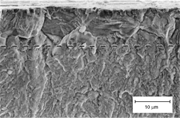
Fig. 21.19 Fatigue crack initiation in carburized coarse-grained 8620 steel (a) quenched directly from carburizing at 927 °C (1700 °F) and (b) reheated after carburizing to 788 °C (1450 °F). Both specimens tempered at 145 °C (300 °F). Scanning electron micrographs. Source: Ref 21.31
More
Image

Published: 01 December 2003
Fig. 12 Fatigue-crack initiation in polystyrene from a V-notch. Note crazes surrounding and preceding the crack. 37×
More
Image

Published: 01 December 2015
Fig. 17 Section showing fretting damage and fatigue crack initiation in 0.2% C steel. Courtesy of R.B. Waterhouse, University of Nottingham
More
Image

Published: 01 November 2012
Fig. 28 Development of extrusions and intrusions during fatigue crack initiation. Source: Ref 8
More
Image

in Common Causes of Failures
> Failure Analysis of Engineering Structures: Methodology and Case Histories
Published: 01 October 2005
Fig. 2.20 Sketch illustrating piston head misalignment, fatigue crack initiation, and propagation. A, region of misalignment; B, sharp corner of piston ring groove; B-C, fatigue crack; and C-D, sudden overload failure
More
Image

Published: 01 March 2006
Fig. 10.28 Fatigue crack initiation at a surface inclusion in 2024-T4 aluminum after 5% of total fatigue life. Source: Ref 10.24
More
Image

Published: 01 August 2005
Fig. A4.3 Comparison of fatigue crack initiation test data and LOOPIN 8 prediction using the uncut spectra. Source: Ref A4.6
More
Image

Published: 01 August 2005
Fig. A4.4 Comparison of fatigue crack initiation test data and LOOPIN 8 prediction using the post -RACETRAK spectra (DMIN = 0.25). Source: Ref A4.6
More
Image

Published: 01 August 2005
Fig. A4.5 Comparison of fatigue crack initiation test data and LOOPIN 8 prediction using the post -RACETRAK spectra (DMIN = 0.50). Source: Ref A4.6
More
Image

Published: 01 December 1999
Fig. 6.39 Composite shear stress range gradient. Fatigue-crack initiation in carburized and hardened gears controlled by the 45 shear stress in zones I and III and by the orthogonal shear stress in zone II. P 0 , maximum pressure at the surface; b, half the contact width. Source: Ref 53
More
Image

Published: 01 December 1999
Fig. 7.14 Variation of fatigue-crack initiation lives with residual stress at the notch of tested steels. Source: Ref 27
More
Image

Published: 01 September 2005
Fig. 10 Intergranular bending fatigue crack initiation at the surface of a gas-carburized and direct-cooled SAE 8719 steel specimen. Source: Ref 20
More
Image
Published: 01 September 2005
Fig. 20 Bending fatigue crack initiation in gas-carburized and reheated 4320 steel. The dashed line corresponds to maximum depth of surface oxidation, and all fracture below dashed line is transgranular. Source: Ref 28
More
Image

Published: 01 December 1999
Fig. 3.17 Variation of fatigue-crack initiation lives with residual stress at the notch of tested steels. Surface carbon: 0.95 to 1.05%. Hardness 750 to 780 HV. Crack initiation, 5 μm crack at the notch. Source: Ref 25 Steel Carbides Retained austenite Vol% Diameter, μm Spacing
More
Image

in Aerospace Applications—Example Fatigue Problems
> Fatigue and Durability of Metals at High Temperatures
Published: 01 July 2009
Fig. 10.9 Histogram showing fractional fatigue crack-initiation life used to date of existing disks
More
Image
Published: 01 July 1997
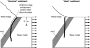
Fig. 2 Conceptual drawing of fatigue crack initiation and growth at the toe of (left) a “Nominal” groove welded butt joint having a substantial (⋍0.1 in. depth) weld discontinuity (slag entrapment) at the root of the critical notch (weld toe) and (right) an “Ideal” weldment with good wetting
More
Image

Published: 01 October 2011
Fig. 16.24 Fatigue failure surface from a piston rod. The fatigue crack initiated near a forging flake at the center and propagated slowly outward. The outer area is the region of final brittle fracture overload. Source: Ref 16.5
More
1