
Skip Nav Destination
Close Modal
Search Results for
ground surface
Update search
Filter
- Title
- Authors
- Author Affiliations
- Full Text
- Abstract
- Keywords
- DOI
- ISBN
- EISBN
- Issue
- ISSN
- EISSN
- Volume
- References
Filter
- Title
- Authors
- Author Affiliations
- Full Text
- Abstract
- Keywords
- DOI
- ISBN
- EISBN
- Issue
- ISSN
- EISSN
- Volume
- References
Filter
- Title
- Authors
- Author Affiliations
- Full Text
- Abstract
- Keywords
- DOI
- ISBN
- EISBN
- Issue
- ISSN
- EISSN
- Volume
- References
Filter
- Title
- Authors
- Author Affiliations
- Full Text
- Abstract
- Keywords
- DOI
- ISBN
- EISBN
- Issue
- ISSN
- EISSN
- Volume
- References
Filter
- Title
- Authors
- Author Affiliations
- Full Text
- Abstract
- Keywords
- DOI
- ISBN
- EISBN
- Issue
- ISSN
- EISSN
- Volume
- References
Filter
- Title
- Authors
- Author Affiliations
- Full Text
- Abstract
- Keywords
- DOI
- ISBN
- EISBN
- Issue
- ISSN
- EISSN
- Volume
- References
NARROW
Format
Topics
Book Series
Date
Availability
1-20 of 1122 Search Results for
ground surface
Follow your search
Access your saved searches in your account
Would you like to receive an alert when new items match your search?
1
Sort by
Image

Published: 01 January 1986
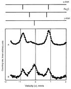
Fig. 5 Backscattered 57 Fe Mössbauer spectra from the lightly ground surface of an iron-iron carbide alloy (NBS Standard Reference Material 493). Only the central region of each spectrum is shown. A, 14.4-keV γ-rays counted; B, conversion electrons counted
More
Image
Published: 30 September 2014
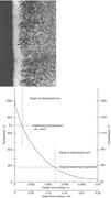
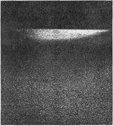
Fig. 80 Temperature distribution within a ground surface, as indicated by microstructural modifications. The A c temperature indicated is for slow heating; at high heating rates, such as encountered in grinding, A c temperatures are elevated. 500×. Source: Ref 43
More
Image
Published: 01 January 2002
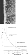
Fig. 88 Temperature distribution within a ground surface, as indicated by microstructural modifications. The Ac temperature indicated is for slow heating; at high heating rates, such as encountered in grinding, the Ac temperatures are elevated. 500×. Source: Ref 30
More
Image
Published: 15 December 2019
Fig. 5 Backscattered 57 Fe Mössbauer spectra from the lightly ground surface of an iron-iron carbide alloy (National Institute of Standards and Technology Standard Reference Material 493). Only the central region of each spectrum is shown. A, 14.4 keV γ-rays counted; B, conversion electrons
More
Image
Published: 01 January 1994
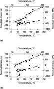
Fig. 11 Variation of surface residual stresses with grinding temperature in ground surfaces of 52100 steel. ○, aluminum oxide 60 J6; •, aluminum oxide 100 H6; ▪ cubic boron nitride. (a) Residual stress perpendicular to grinding. (b) Residual stress parallel to grinding
More
Image

Published: 01 January 2000
Fig. 9 Resistance to galling of Stellite alloy No. 6 (surface ground counterface) versus selected materials. Source: Ref 20
More
Image
Published: 01 November 1995
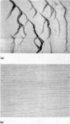
Fig. 9 Comparison of the surface finish of sapphire (Al 2 O 3 ) ground by two different production techniques. (a) Surface grinding, which produced cracks visible on surface. (b) Creep-feed grinding, which yielded no detectable cracks
More
Image

Published: 01 January 2003
Fig. 1 Mild steel ball wear as a function of surface area change of ground magnetic taconite. On ends of plotted lines are the grinding times in minutes. Source Ref 6 , 7 , 10 .
More
Image
Published: 01 August 2018
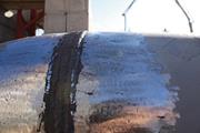
Fig. 8 Ground weld surface after visual inspection and prior to using a subsequent different nondestructive testing method. Courtesy of A. Antonatos
More
Image
in X-Ray Diffraction Residual Stress Measurement in Failure Analysis
> Failure Analysis and Prevention
Published: 01 January 2002
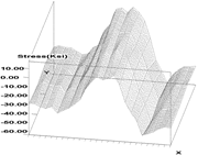
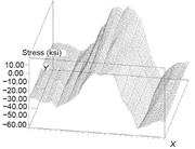
Fig. 10 Surface residual-stress map of resistance welded, heat treated, and ground steel saw blade. Source: Ref 30
More
Image
in X-Ray Diffraction Residual-Stress Measurement in Failure Analysis
> Failure Analysis and Prevention
Published: 15 January 2021
Fig. 10 Surface residual-stress map of resistance-welded, heat-treated, and ground steel saw blade. Source: Ref 39
More
Image
Published: 31 December 2017
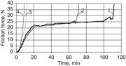
Fig. 41 Effect of dimple depth on the wear life of solid lubricant film (1 = depth of 4 µm, load of 666 N (150 lbf); 2 = depth of 2 µm, load 666 N; 3 = ground surface, Ra = 0.6−0.7 µm, load 306 N (69 lbf); 4 = ground surface, Ra = 0.3−0.4 µm, load 126 N, or 28 lbf). Source: Ref 175
More
Image

Published: 01 January 1989
Fig. 7 Tungsten carbide components having surfaces machined with diamond abrasives. (a) Variety of parts having machined surfaces. (b) Variety of solid carbide twist drills. (c) Carbide reamer having ground helical grooves. (d) Indexable carbide inserts having ground surfaces
More
Image
Published: 01 January 2002
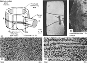
indication of an incipient crack. (b) Fracture surface, with beach marks indicating fracture origin at rough-ground surface. (c) Normal, homogeneous structure of an unused rod examined for comparison; this structure contains equal amounts of ferrite (light) and pearlite (dark). (d) Unsatisfactory structure
More
Image
Published: 01 January 2002
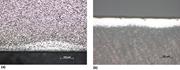
Fig. 12(b) Photomicrograph of the ground parts shown in Fig. 12(a) . A reaustenitized region (white) and a back-tempered zone (dark) at the ground surface are shown. Etched with 3% nital. 70×
More
Image

Published: 30 August 2021
Fig. 12 (a) Two AISI A6 tool steel parts that shattered during finish (abusive) grinding. (b) Micrograph of the ground parts showing a reaustenitized region (white) and a back-tempered zone (dark) at the ground surface. Etched with 3% nital. Original magnification: 70×
More
Image

Published: 01 January 1989
Image
Published: 15 January 2021
Fig. 39 (a) Ti-6Al-4V fastener with grinding burn on the bearing surface. Material has been re-solution treated. 2% HF etch. (b) Ground surface of 5160H steel spring caused as-quenched martensite with 67 HRC Rockwell hardness, while base is 51 HRC. Nital etch
More
Book: Surface Engineering
Series: ASM Handbook
Volume: 5
Publisher: ASM International
Published: 01 January 1994
DOI: 10.31399/asm.hb.v05.a0001239
EISBN: 978-1-62708-170-2
.... The surface finish (roughness average, or R a ) on ground surfaces is typically in the range of 0.2 to 1 μm, whereas lapped and polished surfaces can have R a values of less than 0.05 μm. The material removal rates in lapping and polishing are usually an order of magnitude less than in grinding...
Abstract
Thermal phenomena play a key role in the mechanics of surface finishing processes. This article provides information on the analysis and measurement of temperatures and associated thermal damage generated by finishing processes that are essential to the production of engineered components with controlled surface properties. Emphasis is placed on kinematically simple configurations of finishing processes, such as surface grinding, flat surface polishing, and lapping.
Book: Surface Engineering
Series: ASM Handbook
Volume: 5
Publisher: ASM International
Published: 01 January 1994
DOI: 10.31399/asm.hb.v05.a0001236
EISBN: 978-1-62708-170-2
... and noncontact techniques, and the focus-follow method. Examples of different types of parameters obtained and how they are applied can best be described by discussing the various types of surfaces generated by finishing methods. The surfaces include ground, turned, and milled machined surfaces; surfaces...
Abstract
Most surfaces have regular and irregular spacings that tend to form a pattern or texture on the surface. This article provides information on the general background of surface topography and discusses the different methods for measuring surface topography, namely, contact and noncontact techniques, and the focus-follow method. Examples of different types of parameters obtained and how they are applied can best be described by discussing the various types of surfaces generated by finishing methods. The surfaces include ground, turned, and milled machined surfaces; surfaces subjected to stress; bearing surfaces; plateau honed and tapped surfaces; and reflective, painted, elastic, and wear-resistant surfaces.
1